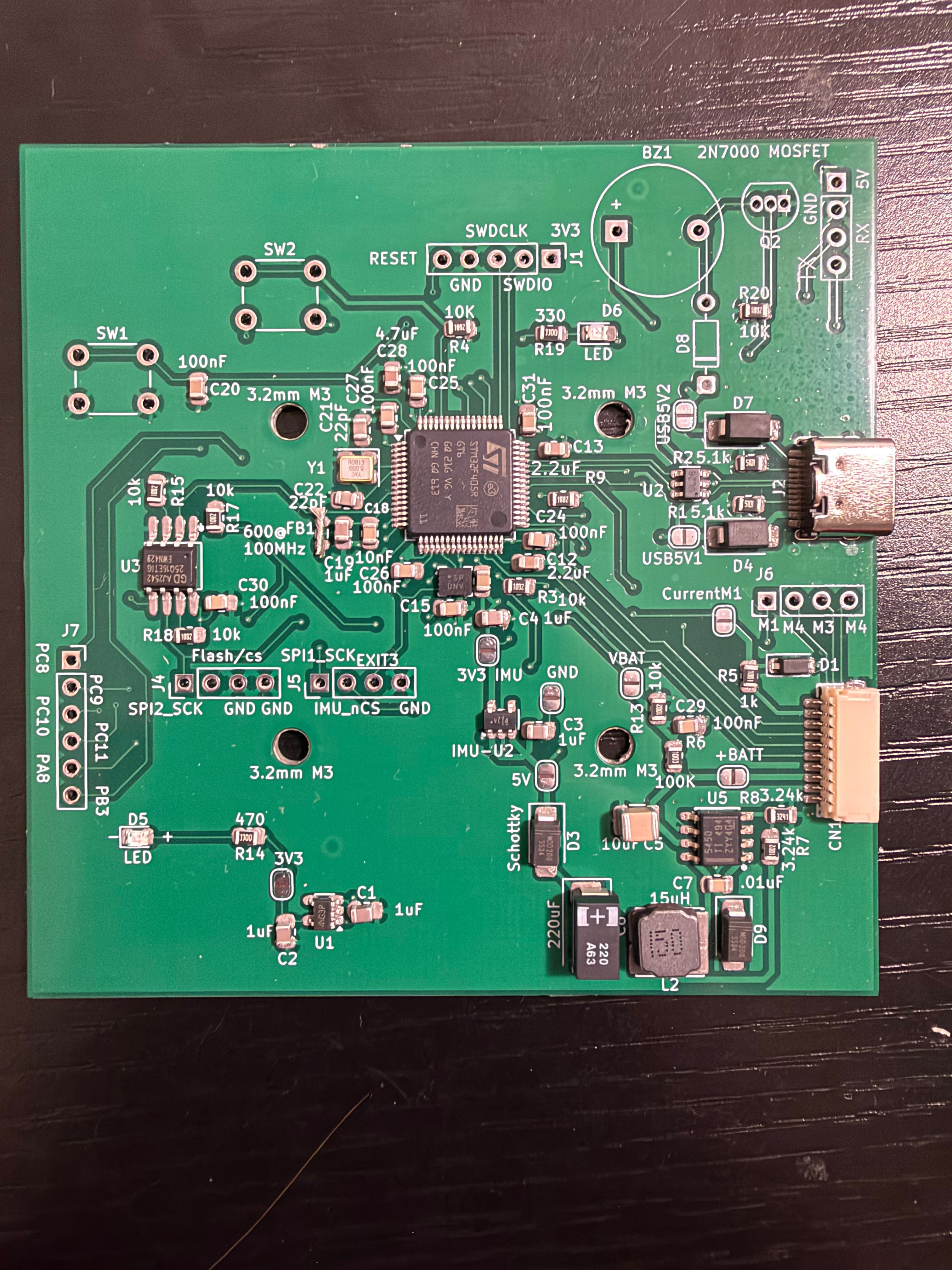
Featured Project 01
Academic Project — Microcontrollers

Dual-Factor Hardware Security System

MCUATmega328PBLANGUAGEBare-Metal CTOOLCHAINAVR-GCCINTERFACEUART + PWM
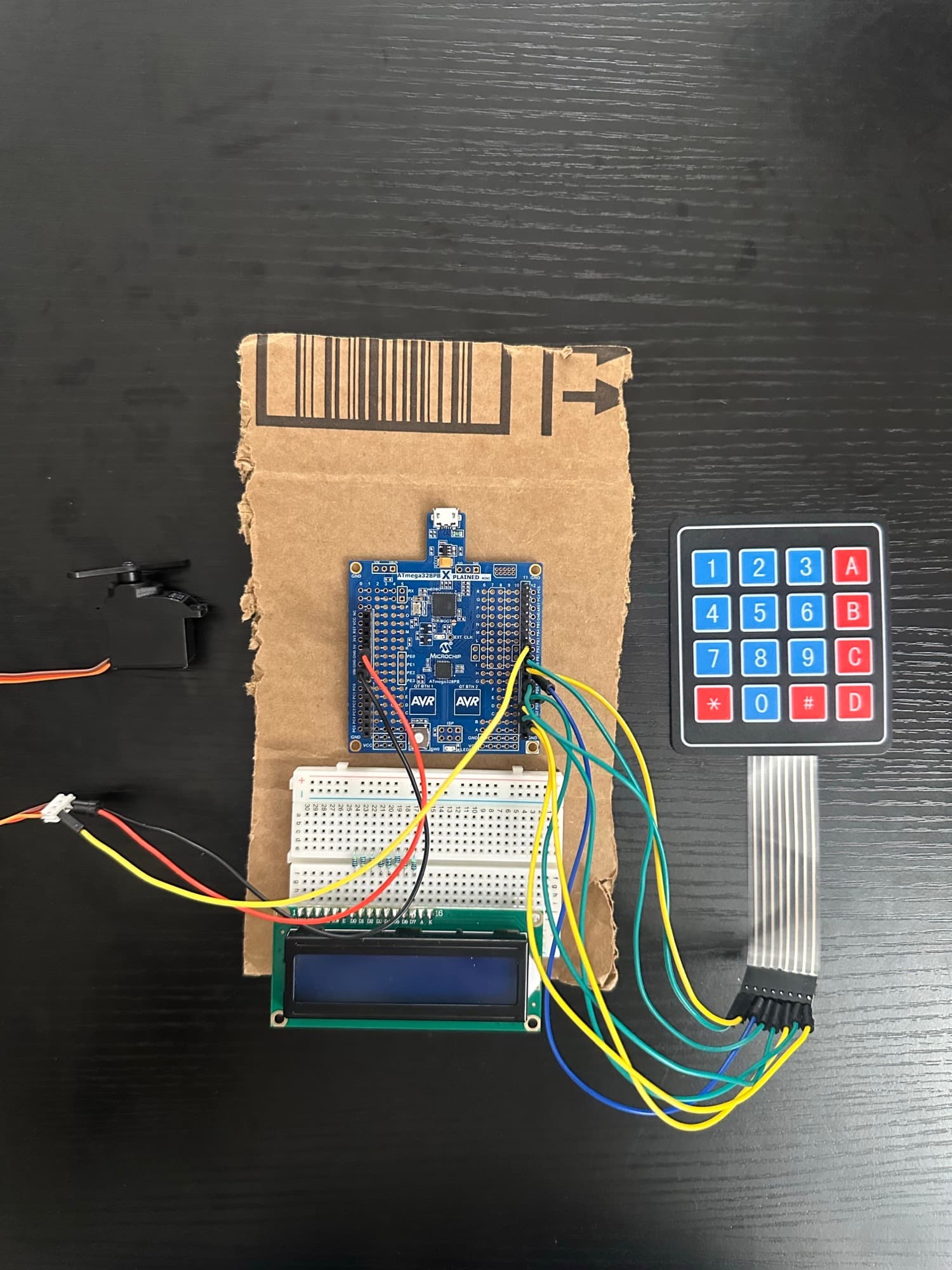
ATmega328PB Door Lock Hardware Prototype
Hardware Prototype
Overview

Implemented a two-factor authentication lock in bare-metal C on an ATmega328PB Xplained Mini. A 4x4 membrane switch keypad feeds a 30ms software debouncer that filters contact bounce on each keypress. A strcmp() call checks the entered 4-digit code, and on match, the firmware sends a prompt over UART to a connected terminal for a second password. A correct password triggers Timer1 in Fast PWM mode to output a 2.0ms duty-cycle pulse, actuating a Datan B1122 servo to unlock for 5 seconds. State transitions are managed entirely through ISRs.

Implementation
Debouncer30ms software debounce loop per keypress on 4x4 membrane matrix
Code Matchstrcmp() against stored 4-digit entry; immediate retry on mismatch
UARTuart_putstr() prompt for second factor; password verified before actuating servo
ActuationTimer1 Fast PWM, 2.0ms pulse to Datan B1122 servo, 5-second unlock window
View Code on GitHub
Featured Project 02
Academic Capstone — Digital Design

FPGA Hierarchical ALU & 7-Segment Display Controller

BOARDArtix-7 Basys3LANGUAGEVHDLTOOLCHAINXilinx Vivado 2024.2DEBUGILA
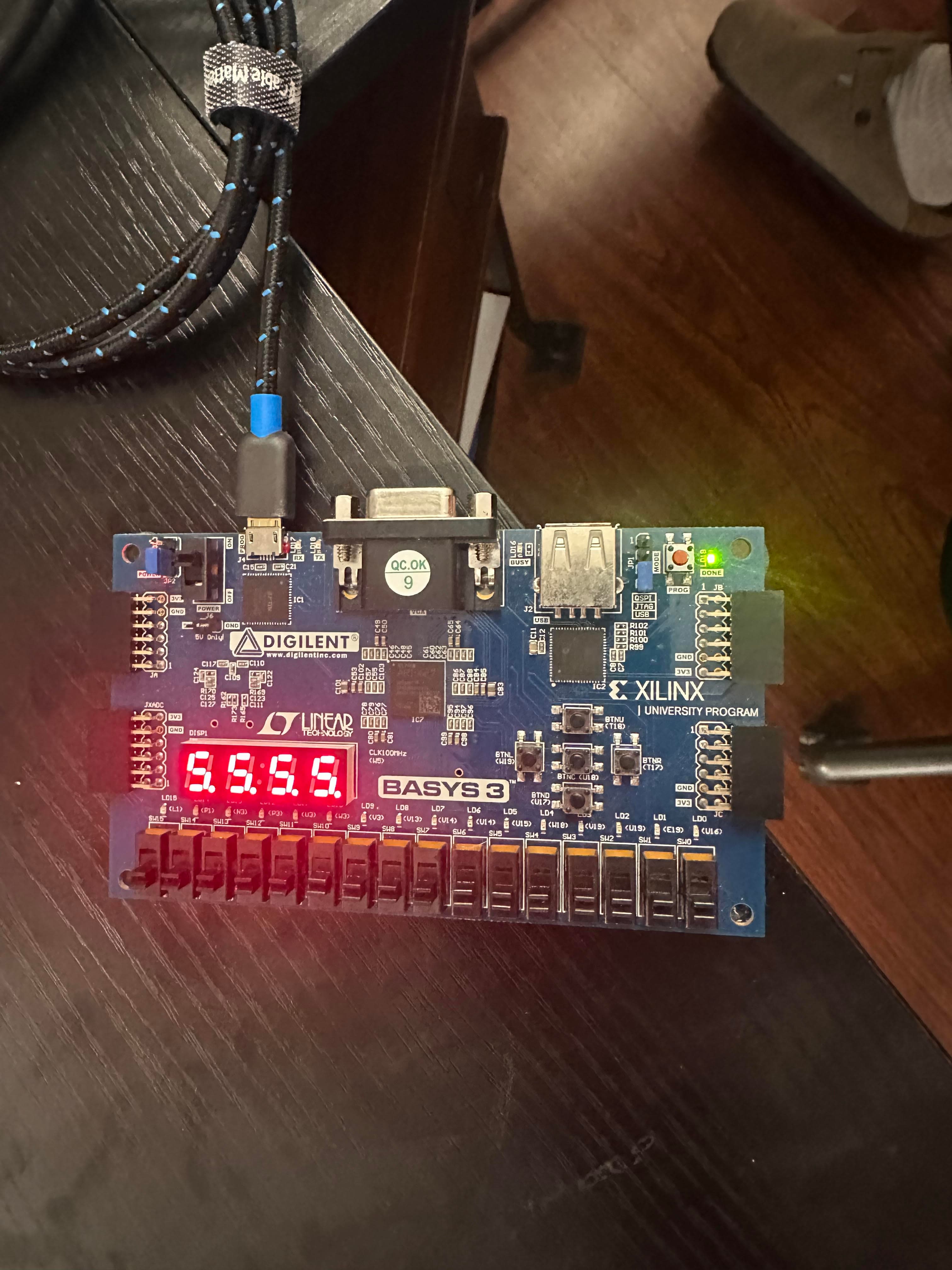
Basys3 FPGA Production Board
Hardware — Basys3 FPGA
Overview

Designed and implemented a 10-bit synchronous up/down counter in VHDL on an Artix-7 Basys3, integrating four modular subcomponents into a synthesized top-level architecture. The counter operates over a 0-to-1000 range, with each clock pulse triggered manually via the debounced center push button (BTNC). Direction (SW13), synchronous preset from SW0–SW9 (SW14), and asynchronous reset (SW15) are all switch-controlled. The binary output is converted to four-digit BCD by a standalone converter, then displayed on the 7-segment array via time-division multiplexing.

Implementation
Debouncer16-bit shift register clocked at 100MHz; output changes state only on all-high or all-low shift register, suppressing contact bounce on BTNC
Counter10-bit synchronous design with async reset priority, synchronous preset with overflow clamping to 1000, and up/down wraparound logic
BCD ConverterInteger division and modulo on CONV_INTEGER output; results packed into 16-bit BCD vector
SSD Driver20-bit free-running counter; top 2 bits select active digit and anode; 100MHz refresh
VerificationEach submodule verified with dedicated testbenches (signal assertions, waveform inspection) before top-level integration in Vivado
Footprint117 / 20,800 Artix-7 logic slices utilized post-synthesis
View Code on GitHub
Academic Project — Integrated Circuits

CMOS VLSI Physical Layout & Delay Analysis

TOOLTanner L-EditSIMT-SpiceVERIFYDRC/LVSPROCESS250nm Process
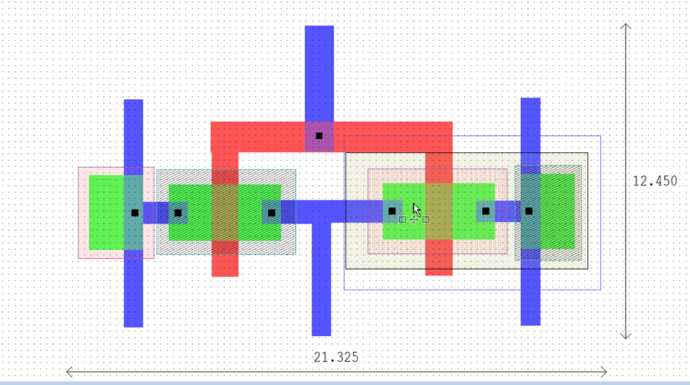
CMOS Inverter Physical Layout in Tanner L-Edit
Inverter Physical Layout
Overview

Designed and verified a complete CMOS cell library from scratch in Tanner EDA, targeting a 250nm process (Generic_250nm_Devices, W/L = 1.5μm/250nm), progressing from individual transistor layouts up to a 2-bit parallel adder placed within a full pad frame.

Architecture

The CMOS inverter cell was laid out manually at 21.3 × 12.5 μm, confirmed with DRC, then re-generated via Schematic Driven Layout (SDL) from a T-Spice netlist export to cross-validate both flows. DC sweep produced a VTC with a switching threshold near 1.7V — below the ideal 2.5V midpoint due to the NMOS electron mobility advantage over the matched-width PMOS. Transient simulation at 50 MHz (20ns period, 1ns rise/fall) confirmed clean inversion. Subsequent labs added NAND/NOR, transmission gate, and D flip-flop cells, all reused as subcomponents in the final design: a 2-bit parallel adder (2 FA, 8 DFF, 3 TG, 1 inverter) placed within a pad frame, with a WRITE-controlled transmission gate output buffer and synchronous CK/_CK control interface.

View Code on GitHub
Competition Build — Autonomous Systems

Autonomous Vision-Guided Robotics Platform

LANGUAGEC / kiprALGOPID ControlVISIONOpenCVANALYSISMATLAB
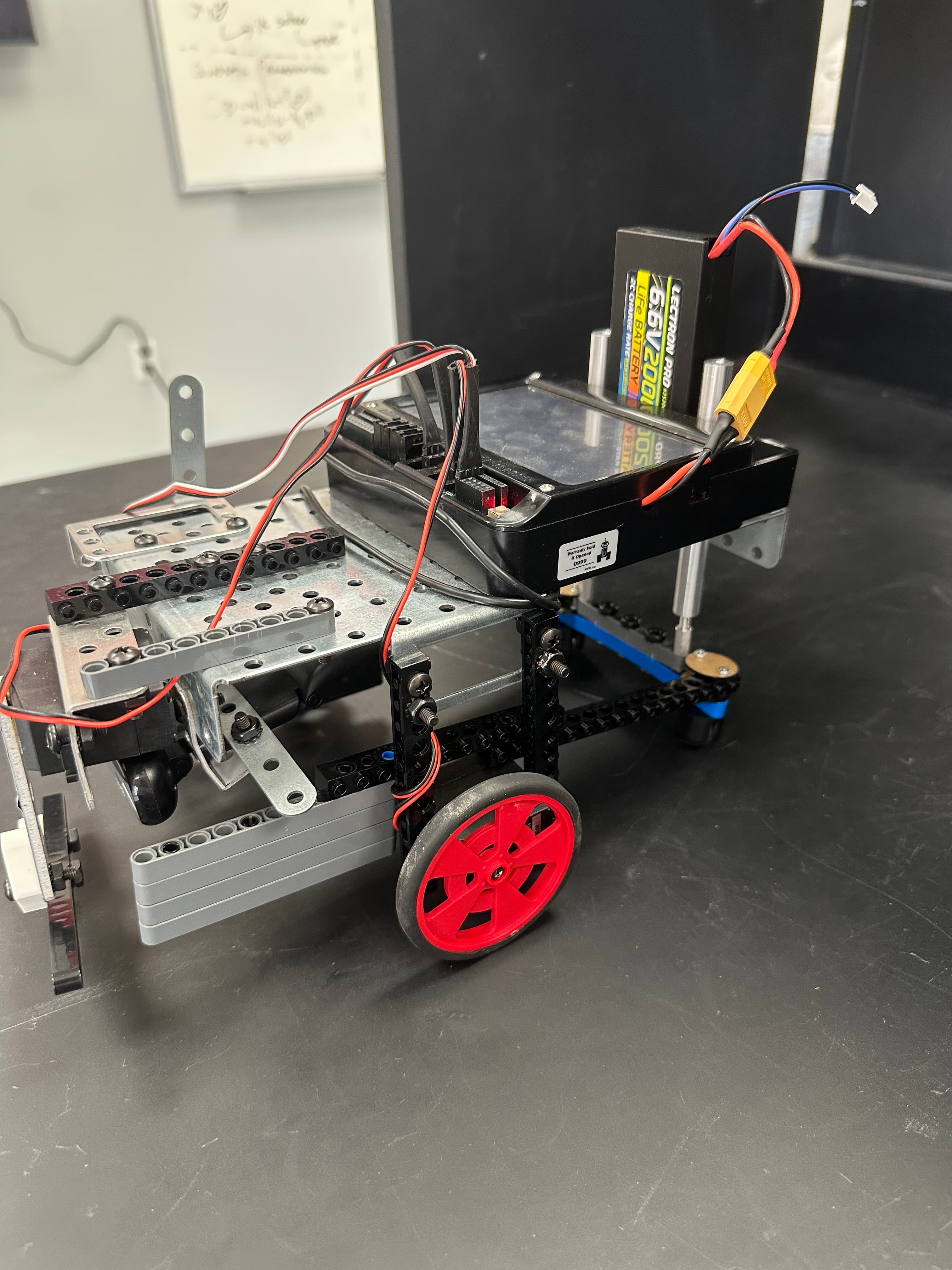
Final Robot — Side Profile
Final Competition Chassis
Overview

Wrote the C-based control firmware for an autonomous mobile robot on a Wallaby controller (kipr/wombat.h) with touch sensors, IR reflectance, CdS photoresistors, an E.T. distance sensor, and a USB camera.

Architecture

Labs built up through reactive, Braitenberg, and closed-loop control paradigms. Lab 3 fused touch-sensor obstacle avoidance with IR-based line following into a single behavior-priority loop. Lab 4 implemented a Braitenberg light-follower: raw CdS readings (100–4000 range) normalized to 0–100% motor power, with a meta-sensing counter that detected repetitive bump cycles within a fixed time window and injected a random escape maneuver to break the loop. Lab 5 added a PID wall-following controller using the E.T./IR sensor, with data logged to arrays and plotted in MATLAB to compare P-gain values.

Competition Notes

Final competition: the robot autonomously collected color-coded cubes on a 4×6 ft arena, reading QR codes at the arena corners to determine the target cube color, and used a floor luminosity gradient to identify the home zone. 2-minute autonomous collection window. 1st place finish.

View Code on GitHub
Back to Home↑ Top